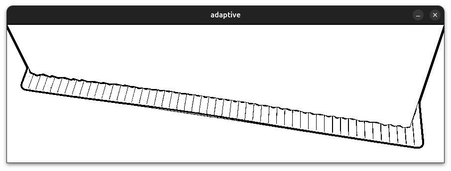
Today I implemented a new way of correcting the angles of the rectangle. Basically, you correct the angles by the "regional" median -- an median value calculated only with the rectangles with certain regions. This system allows more accurate correction of the error, as the difference in angles tends to be grouped together (because of some camera distortion or perspectives).
We divide keys' rectangles into number of groups(default 5 groups) and calculate the median of angles of the rectangles inside those regions.
    ...
    // calculate the regional median
    std::vector<std::vector<RotatedRect>>rect_divided_by_region;
    std::vector<int>angle_region_indicator;
    int region_count = 5;
    double angle_regional_median[region_count];
    region_divider<RotatedRect>(keys_info.keys_rectangle_list , region_count , rect_divided_by_region , angle_region_indicator);
    for(int i = 0; i < region_count; i++) {
        std::vector<double>median_list;
        for(RotatedRect rr : rect_divided_by_region[i]) { median_list.push_back(rr.angle); }
        if(median_list.size() != 0) {
            angle_regional_median[i] = calculate_median(median_list);
        }
    }
    ...
Now we loop through the list of rectangles, find the outliers and adjust them to the regional median. I used the left and right whiskers values from the quartiles to determine the outliers.
/* removed debug messages for convenience */
void PianoRecognition::adjust_key_angles(struct piano_keys_info &keys_info) {
    ...
    double Q1 = calculate_percentile(rect_angle_list , 0.25);
    double Q3 = calculate_percentile(rect_angle_list , 0.75);
    double left_whisker = Q1-1.5*(Q3-Q1);
    double right_whisker = Q3+1.5*(Q3-Q1);
    ...
    /* calculating the regional median */
    ...
    for(int i = 0; i < keys_info.keys_rectangle_list.size(); i++) {
        // if above the right whisker / below the left whisker
        if(keys_info.keys_rectangle_list[i].angle >= right_whisker||keys_info.keys_rectangle_list[i].angle <= left_whisker) {
            // rotate the rectangle by its pivot
            Point2f pts[4];
            RotatedRect rr = keys_info.keys_rectangle_list[i];

            rr.points(pts);
            double target_angle = angle_regional_median[angle_region_indicator[i]];
            double delta_theta = target_angle-rr.angle;

            int x0 , y0;
            // use midpoint of two corner points
            x0 = rr.center.x+(rr.size.height/2)*sin(rr.angle*M_PI/180.0f);
            y0 = rr.center.y-(rr.size.height/2)*cos(rr.angle*M_PI/180.0f)
            int x = keys_info.keys_rectangle_list[i].center.x , y = keys_info.keys_rectangle_list[i].center.y;

            int rotated_x = (x-x0)*cos(delta_theta*M_PI/180.0f)-(y-y0)*sin(delta_theta*M_PI/180.0f);
            int rotated_y = (x-x0)*sin(delta_theta*M_PI/180.0f)+(y-y0)*cos(delta_theta*M_PI/180.0f);
            rotated_x += x0; rotated_y += y0;

            keys_info.keys_rectangle_list[i].center.x = rotated_x;
            keys_info.keys_rectangle_list[i].center.y = rotated_y;

            keys_info.keys_rectangle_list[i].angle = target_angle;

        }
    }
}
Basically, the code above uses the regional median as the new angle value for adjustment. The angle_region_indicator array serves the purpose of interpreting the array index into index for regional median array (which looks like [0,0,0,0,0,0,0,0,1,1,1,1,1,1,1,1,2,2,2,2,2,2,2,2,....].) The center of mass is then rotated by the pivot point, and the angle of the rectangle is adjusted to the regional median angle.
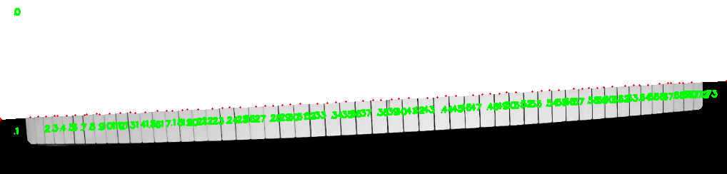
I also changed the outlier detection system (finally!) Now the system uses best fit line to determine what contours to remove. The system first creates a best-fit line of the center of masses of the rectangles and removes all the rectangles that do not intersect with the line. This method does not rely on the size of the rectangle in determining the outlier, making it more accurate and robust.
    ...
    // calculate the best fit line of C.M. from the rectangles that are not height adjusted
    // this way we can remove the outliers prematurely
    std::vector<Point>premature_center_points;
    for(RotatedRect r : keys_rect_list_1) { premature_center_points.push_back(r.center); }
    Vec4f premature_best_fit_line;
    fitLine(premature_center_points , premature_best_fit_line , DIST_L2 , 0 , 0.01 , 0.01);

    // reuse previously used variables
    bestfit_vx = premature_best_fit_line[0] , bestfit_vy = premature_best_fit_line[1] , bestfit_x0 = premature_best_fit_line[2] , bestfit_y0 = premature_best_fit_line[3];
    bestfit_b = bestfit_vy/bestfit_vx;
    bestfit_a = -(bestfit_b*bestfit_x0)+bestfit_y0;

    std::vector<Point>bestfit_contour = {Point2f(0 , bestfit_a) , Point2f(0 , bestfit_a+1)
     , Point2f(piano_image_padding.size().width , (double)piano_image_padding.size().width*bestfit_b+bestfit_a+1)
     , Point2f(piano_image_padding.size().width , (double)piano_image_padding.size().width*bestfit_b+bestfit_a)};

    std::vector<RotatedRect>keys_rect_list_2;
    for(int i = 0; i < keys_rect_list_1.size(); i++) {
        std::vector<Point>contour;

        // slightly inflate the size for detection
        keys_rect_list_1[i].size.width  *= 1.5;
        keys_rect_list_1[i].size.height *= 1.5;
        Mat overlap_test1 = Mat::zeros(piano_image_padding.size() , CV_8UC1);
        Mat overlap_test2 = Mat::zeros(piano_image_padding.size() , CV_8UC1);

        rotated_rect_to_contour(keys_rect_list_1[i] , contour);
        drawContours(overlap_test1 , std::vector<std::vector<Point>>({bestfit_contour}) , -1 , Scalar(0xff) , -1);
        drawContours(overlap_test2 , std::vector<std::vector<Point>>({contour}) , -1 , Scalar(0xff) , -1);
        Mat test = overlap_test1 & overlap_test2;

        keys_rect_list_1[i].size.width  /= 1.5;
        keys_rect_list_1[i].size.height /= 1.5;

        if(countNonZero(test) >= 1) {
            keys_rect_list_2.push_back(keys_rect_list_1[i]);
        }
        overlap_test1.release();
        overlap_test2.release();
        test.release();
    }
For determining whether a rectangle intersects with a line, I just used the straightforward way of converting the line as contour and brute-forcefully drawing them into the canvas. Surprisingly, that method smoothly worked! I am so happy to finally fix the problem that lingered me from the start of this project...
I also changed the method of masking the black keyboard from the image. Originally, I made a polygon that encompasses the black keyboard, which starts from the top left corner and ends at the top right corner. Making the polygon's corner top left and right sometimes did not perfectly covered all the areas of the keyboard, resulting in imperfect shapes of keyboards. I finally fixed this problem by adjusting the start and end-points with the best fit line.
If we get the best-fit line for the endpoints of black rectangles and apply it to the mask... we get this perfect mask :
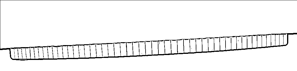
It's fairly simple... get the best fit line, get the two right and left coordinates and insert them into the contour.