Today I designed the register unit. Based on the design from the previous 16-bit computer, I slightly modified the architecture so that it's more easier to implement on breadboard.
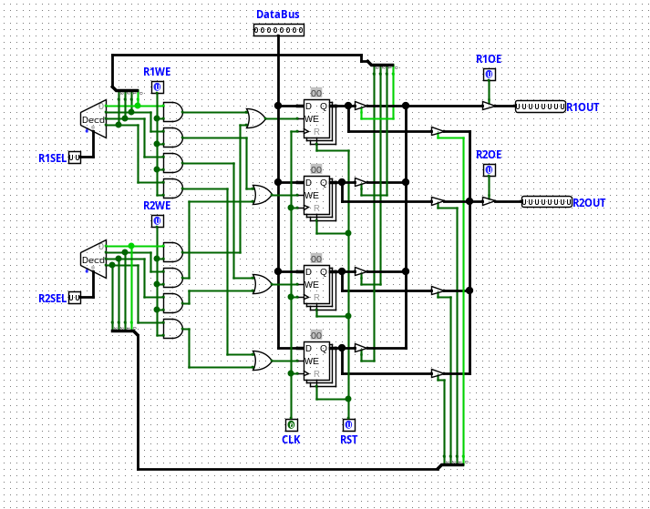
The primary role of the register unit is to have two register selector and two output so that we can simultaneously access to two registers. This design can make life whole lot easier, as implementing instructions like "MOV R0, R1" becomes very simple.
Unlike the previous design that over-used multiplexers, we only have controller BUS gates(which will be 74LS245 IC in practice) to control the flow of the data. We can use the fact that 74LS45 IC supports high-impedence state(basically floating state) and connect all the outputs of the bus together. Since the decoder only activates one bit among the four, we can safely ensure that the BUS signals will mutually be exclusive with each other.
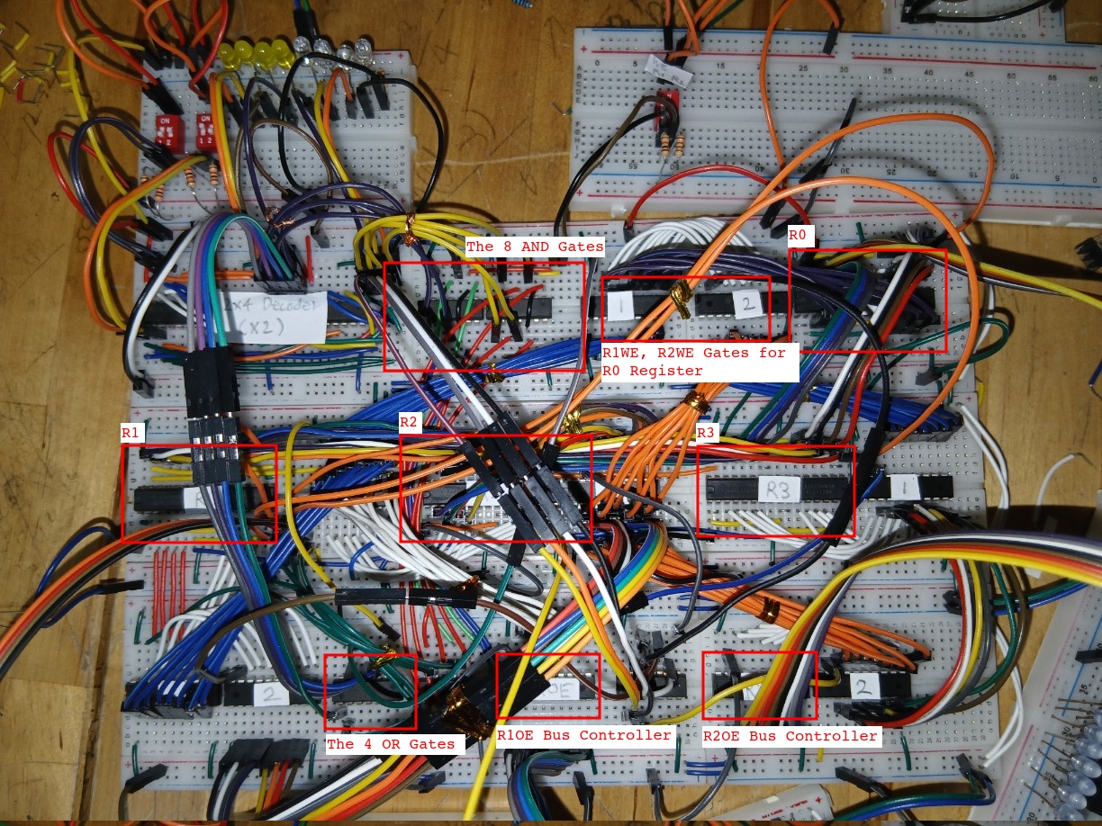
Yes, I have lots of spare time on my hands. I built this in a day and half.
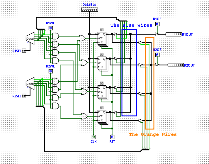
Those blue wires and orange wires that are tied with each other are the wires that connect the bus output of each registers. It was quite a pain in the ass to wire all these things up...
I used 74LS173 for all the register ICs, and dozens of 74LSxx for decoders and bunch of AND and OR gates. Since 74LS173's WE(Write Enable) pin is inverted, I had to use NOR gates(74LS02) instead of just OR gates.
The 74LS173 module actually has its own OE(output enable) pin, but I actually didn't use them and just made every register output their value unconditionally(because that way the register's output behavior is equivalent to those in Logisim simulator.)
We're off to good start so far!
Tomorrow, I'm going to make the EEPROM(AT28C256) programmer from Arduino Nano.