Today I had to struggle with some weird behaivor that the program counter was doing. 74LS161 is "supposed" to increment the counter "only" when the clock is at rising edge, but for some weird reason, 74LS161 incremented the counter both at the rising and falling edge!
This weird occurence just kept happening so sporadically, so I tried solving this problem with more analytical approach,, by making a makeshift oscilloscope with Arduino!!
You see, Arduino IDE has quite a useful tool called "Serial Plotter," which graphically plots the data coming from the serial for you, just like the oscilloscope(but with severely scarce functionalities.)
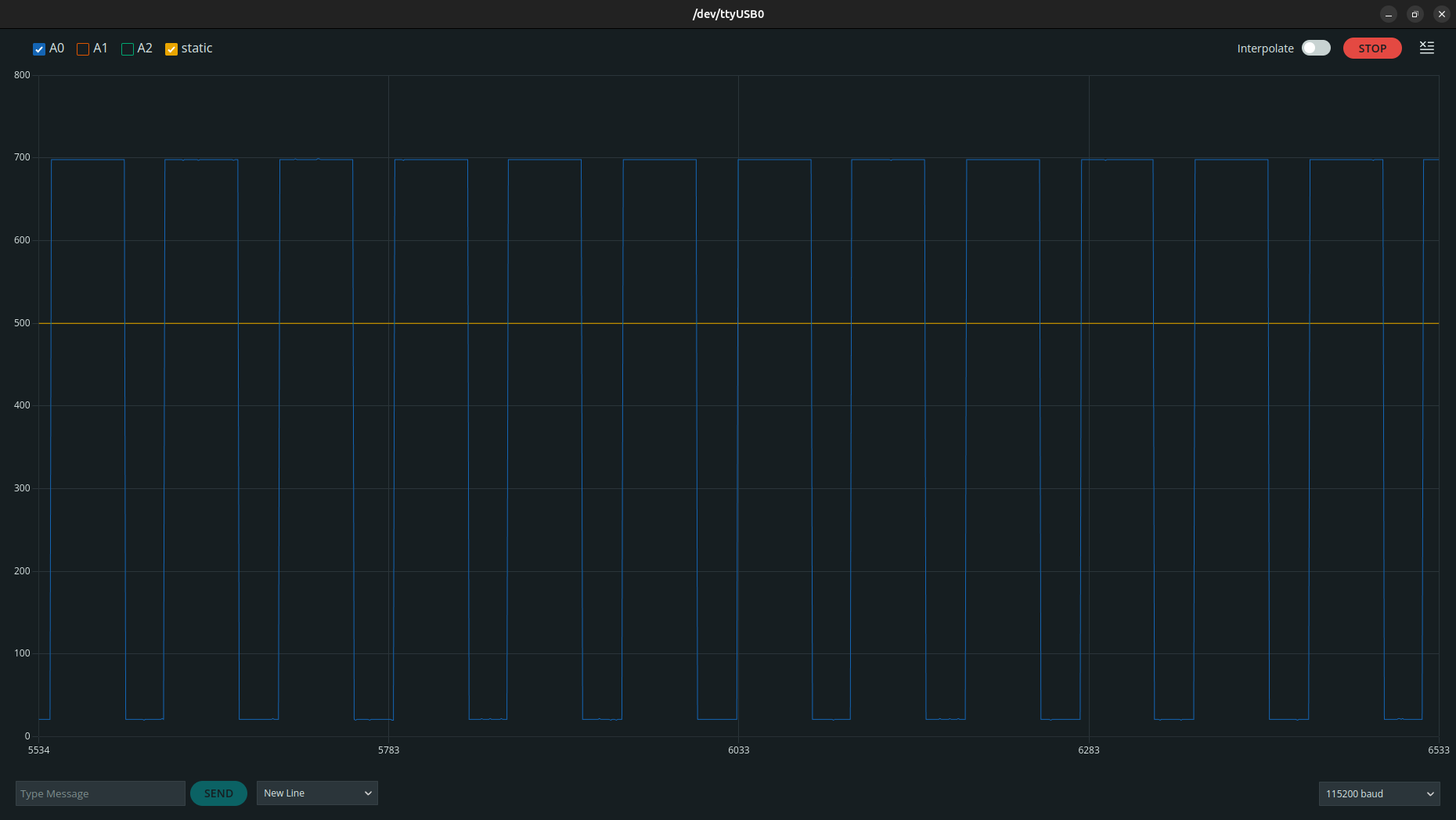
Neat, huh!
The code is fairly simple! Read the analog signal from the arduino's port, print them in a matter that the serial plotter can understand.
int num_of_inputs = 3;

void setup() {
  Serial.begin(115200);
}

int static_val = 500;

void loop() {
  for(int i = 0; i < num_of_inputs; i++) {
    int val = analogRead(i);
    Serial.print("A");
    Serial.print(i);
    Serial.print(":");
    Serial.print(val);
    Serial.print(",");
  }
  Serial.print("static:");
  Serial.println(static_val);
}
Note that you have to label each variable upon sending the data, otherwise the plotter won't understand it.
Here, the baudrate of the serial determines the speed in which the signal is being plotted(which totally makes sense if you consider it.) If you want your monitoring to be a little bit slower, you can do that by just lowering the baudrate.
Upon analyzing the signal, I realized that I actually forgot to set the Enable P and Enable T pin to HIGH(duh)... so I did but the problem still persisted. Well, I highly suspect that this also contributed in making this weird bug..
When I analyzed the inverted Reset signal(inverted by 74LS04), I noticed that although the signal was high, there was some weird synchronized noise that came along with it!
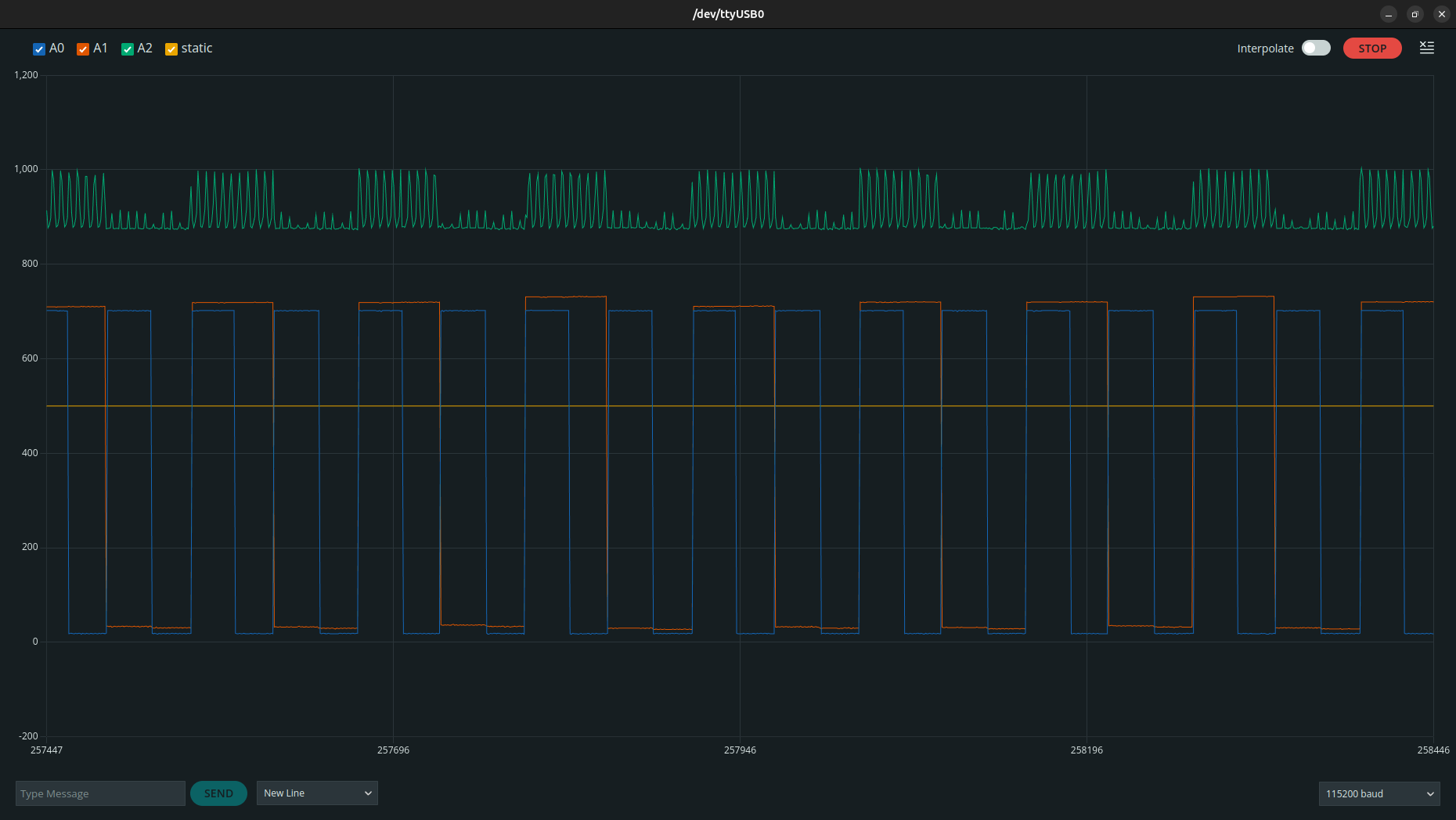
A0 is the clock signal from NE555, A1 is the first bit of the counter, and A2 is the inverted reset signal that's going into the 74LS161.
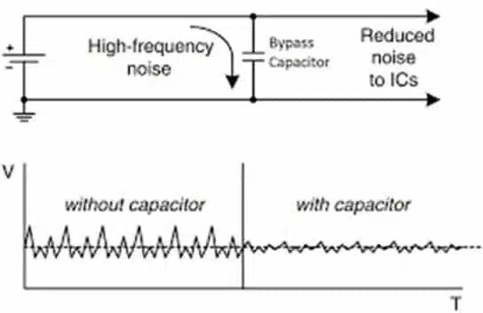
I searched up how to reduce the noise of the signal and found out that by simply adding a capacitor you can just eliminate the noise in the digital signal! So I tried it right away. The result was just astonishing!
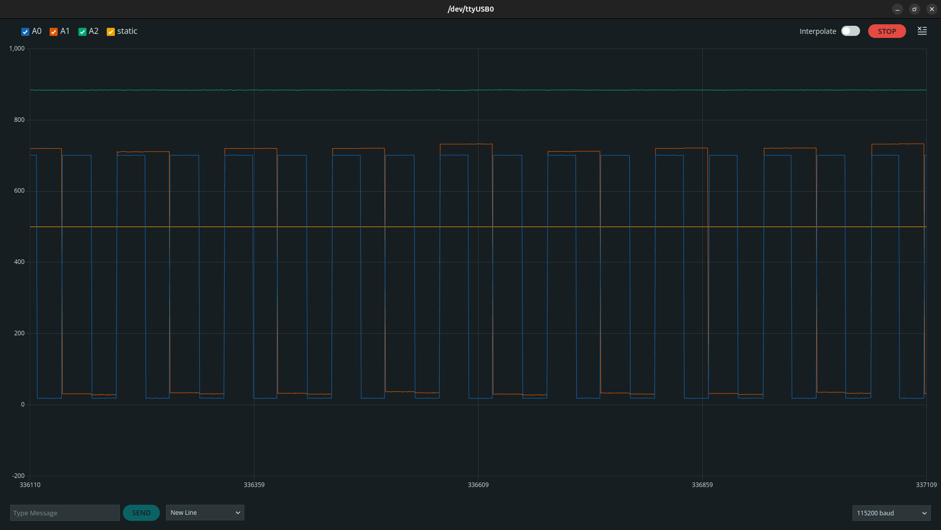
Voilà!
More specifically talking, I added a capacitor between the signal and ground, which I now know that it's called a "Bypass Capacitor." Gosh, people are super smart..
Anyway, just to be extra safe, I added two 0.1μF ceramic capacitor across the VCC and GND, as I felt like the 555's clock signal also creates some interferences in the main VCC and GND line. For the bypass capacitor for inverted reset signal, I used 22μF electrolytic capacitor(to be frank, those values(0.1μF, 22μF) are just utterly arbitrary!)
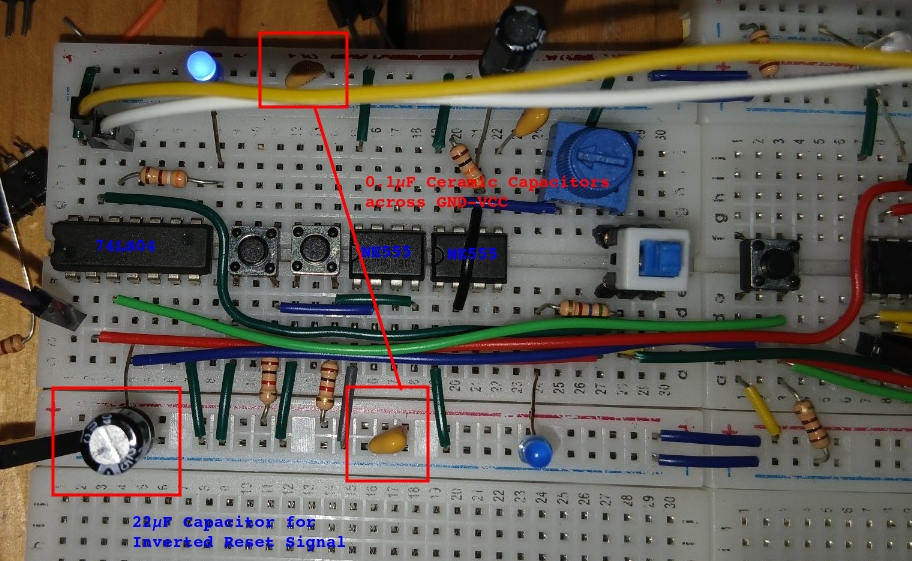
Crap, the text next to the electrolytic capacitor was supposed to be red!
And thankfully, after adding the capacitors, the counter module works like a charm!